Pi-based multi-prop trigger for animatronics, Part 2

Back in March I wrote about a Pi-based controller for multiple Halloween props. As I go the props ready this year, I realized three things: 1) I wanted to change the routine from what I planned, 2) The way I needed to connect this particular set of props was different than what I’d been planning and 3) it turns out I couldn’t use an electromechanical relay board to react to the trigger signal from the Pi to one of the skeletons, because it holds open too long. So, back to the drawing board, as well as desoldering and resoldering.

My setup for this year includes two skeletons talking to one another. One is a simple talking pose-and-stay type of skeleton, with light up eyes and a moving jaw driven by a motor. The other is a talking and moving skeleton prop called Grim. Besides wanting movement to trigger them, I needed to be able to provided custom audio phrases for them to say to one another.

Talking Skeleton

The talking skeleton [insert photo] uses a motor to drive the jaw movement, and has light up LED eyes. In order to allow for custom audio, I disconnected the built in sensor and sounds and connected a commercial audio controller called a Jemmy Talk. The Gemmy Talk takes line level audio input and sends out voltages to move the motor. It also has a pass through for the audio, so that you can send line level output to an amplifier. I don’t use this latter feature in my set up. I use a DFPlayer MP3 player as my audio source. It has both a line level output, which I feed to the Jemmy Talk, and amplified audio that I feed directly to the speaker built into the skeleton. The board with the DFPlayer is also where the power is supplied, through a barrel jack connector to a 5V supply. The button switch on the board is to test things without requiring an external trigger signal. The two 3-pin connectors on the board are not used. The three boards are shown in the picture. Besides the Jemmy Talk and the board with the DFPlayer, the third board receives the triggers from a Raspberry Pi (see “Controller,” below).

Picture showing the audio source and controls for the skeleton, showing the Jemmy Talk board, the board with the DFPlayer MP3 player, and the board with input from an external controller and Darlington array. All are wired together as they are when in use.

The audio source and controls for the skeleton, showing the Jemmy Talk board, the board with the DFPlayer MP3 player, and the board with input from an external controller and Darlington array.

The circuit board on the bottom will receive the triggers from a Raspberry Pi (not shown) and features a Darlington ULN2003 transistor array chip that acts as a set of relays to signal the DFPlayer to play the audio and also to turn the skeleton’s eyes on. I had originally used an electro-mechanical relay rather than the Darlington array, but the MP3 player requires that the button press to play the audio be short, and the relay held closed too long when triggered. The MP3 player uses a short drop to ground to signal to play the next track, which is what I needed, while a longer drop on the same pin signals the player to turn up the volume. Had I known that I would be using the Darlington array from the start, rather than a separate relay board, I could have fit everything on just one, rather than two, boards.

If the skeleton was like many, with simple LED eyes, I could have used the Jemmy Talk to control them as well, but it doesn’t. So I kept the Try Me wires connected to trigger the eyes to go on. That is what the second trigger on the Darlington is for. That means that I needed two signals from the Pi, one to turn on the audio and one to light the eyes, but this gives me more flexibility for the future. Here’s a picture of the final circuits in a small project box I printed for the project:

Grim

The Grim prop was modified by adding a Grim Talker board from the same source as the Jemmy Talk. Once that was installed per the directions, I just needed to put the correct new audio file on the SD card that goes into the Grim Talker (no external MP3 player needed) and determine how to trigger it. It can be triggered to activate by either the sensor built into the original Grim prop, by cycling the power on and off, or by a Try Me button switch connected through a 1/8″ MONO cable jack. When triggered, the audio and motion routine starts. The audio will play through completion, but the motion will stop once it’s routine (about 30 seconds) ends. If the audio is longer (as in my case) and you retrigger the prop before the audio ends, the motion will start up again. This is what I wanted to do.

Cycling the power wouldn’t do what I wanted, as it would kill the audio. I didn’t want to mess with the built in PIR sensor, as I may want to use it in the future. And I needed to coordinate Grim with the other skeleton. So that left the try me switch. So the multi-prop controller that I put together (a modification of what I described in the Pi-based controller for multiple Halloween props write-up, uses another Darlington to act as a switch that closes to trigger the prop.

Controller

Pictorial diagram of the controller. PI on the left has connections to the other board for power, one connector to a 3 pin female header on the other board for input from a PIR, and four GPIO output connections (one to a 3 pin header for a PIR type of controlled prop, two to a 3-pin connector for either a PIR control or one needing two separate signal inputs, and one that goes to the input of a ULN2003 Darlington on the board, which is connected to close a connection when triggered.

Raspberry Pi based multi-prop controller

In order to control multiple, coordinated, props from a single motion sensor, I put together a simple circuit that controls up to three props, of a couple of different types. A PIR provides input to the Raspberry Pi, which then sends output signals for up to three props. One output simply closes a switch, and it is good for triggering props through their “try me” button wires (replacing the button / switch). For this, the trigger output from one of the GPIO pins on the Pi triggers a relay in a Darlington. This is a bit of an overkill, as I’m only using one of the eight channels on the Darlington, but it’s cheap, easy to use, and works.

Another GPIO pin sends and output voltage to the sensor wire in a 3 pin servo connector. The grounds also link the prop to the controller to provide a common ground. This works for any prop set up to look for input from a PIR or similar sensor providing a positive low voltage signal. What would normally be the voltage source on a servo connector is left unconnected, as it’s not needed to power anything.

Finally, two other GPIO pins send output to another 3-pin connector, using what would normally be the signal and voltage lines on a servo connector. This is for the talking skeleton as described above, with one signal to start the MP3 audio player and the other to control the eyes. Again, the ground is connected to ensure a common ground. This connector could also be used to simply control a prop that only needs a single signal, rather than two, providing flexibility.

The python controller program for this year is really quite simple:

from gpiozero import DigitalOutputDevice
from gpiozero import MotionSensor
import time

skel_talk = DigitalOutputDevice(23)
skel_try_me = DigitalOutputDevice(24)
grim_trigger = DigitalOutputDevice(25)
pir = MotionSensor(15)

while True:
    pir.wait_for_motion()
    print("motion detected")
    skel_talk.on()
    skel_try_me.on()
    grim_trigger.on()
    time.sleep(0.2)
    skel_talk.off()
    skel_try_me.off()
    grim_trigger.off()
    time.sleep(30)
    print("waited 30 seconds")
    grim_trigger.on()
    time.sleep(0.2)
    grim_trigger.off()
    time.sleep(50)
    print("ready to trigger again")

The program uses the gpiozero library for interfacing with the Pi’s GPIO pins. Three pins are used for outputting signals: named skel_talk to trigger the skeleton’s audio, skel_try_me to trigger the relay to close the skeleton’s try me connection, and grim_trigger to send a trigger signal to the Grim prop. These are all defined as simple DigitalOutpuDevice pins. There is one input pin, named pir, which is defined as a MotionSensor input.

The program is an endless loop which waits for the PIR sensor to be set off. When that happens, the three output triggers are both set high (True) for 0.2 seconds and then set back off. Then the program sleeps for 30 seconds while the Grim motion is running, then the grim_trigger is again set high again for 0.2 seconds to trigger the motion to restart (the audio, which is about 1 minute long, is still running). Finally, the program waits 50 seconds. The audio and motion will continue for approximately 30 of these seconds, with the additional 20 seconds being a dead time so that the props don’t immediately retrigger. The print statements are there simply for initial debugging. I used Crontab to set the script to autorun in the background upon startup. I need to modify the script so that once triggered, it also periodically closes the try me switch on the talking skeleton. At present, the eyes only light for a short time at the start of the dialog.

Results

Here’s the two circuits, in their circuit boxes, and then a video
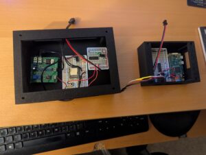
Photo of the electronics for the skeleton in one project box and the pi-based multi-prop controller in a second project box. The skeleton controller has a Jemmy Talk circuit board, a board with the MP3 player, and a third board. The prop controller has a raspberry pi and a board with a Darlington array, source for power, and several female 3-pin headers.

The electronics for the talking skeleton on the left and the Pi-based multi-prop controller on the right.

of the final result in operation. Unfortunately, it’s not a great video clip, but it does show the two skeleton props talking back and forth in a short excerpt from their longer dialog. An mentioned above, I need to add a line or two to the script to periodically retrigger the eyes of the smaller skeleton, so that they stay lit during the whole dialog.

It took more effort than I originally thought it would, partly due to faulty planning on my part, but I think it all came together nicely.

Witch and Cauldron Silhouettes with Coals

Introduction

We have a set of plywood bear silhouettes set up in our backyard for most of the year, visible from our house and from the street through the woods. This year, I decided to make a Halloween scene to replace them when they first go into hibernation for the fall and winter. The bears would be replaced with a witch and her cauldron, and there would be artificial lit coals under the cauldron.

The Silhouettes

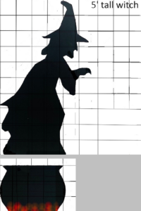
To make the silhouettes, I first needed a pattern. I borrowed a nice outline for the witch

Baack silhouettes of a witch and a cauldron, drawn to scale with vertical and horizontal scaling lines.

Scale drawings of the witch and cauldron

that I found online, modifying it so that it would be easily recognizable, interesting, but within my personal jigsaw skills ability. The cauldron I just drew from scratch. I made scale drawings, with vertical and horizontal scaling lines marking what would be every six inches in the final build.

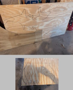
The purpose of the scaling lines was to make it much, much easier to freehand layout the full-size pattern on the plywood. I went from where each line in the outline crossed a scaling line to the next scaling line, hand-drawing in each segment. Once the pattern was drawn on the plywood at scale, I cut both the witch and the cauldron out using a jigsaw.

I primed the silhouettes with flat black spray primer / paint and then painted them with flat black barn paint.

Two images, one of the witch outline and one of the cauldron outline. Each is sketched onto a piece of plywood, along with scaling lines.

The outlines sketched onto the plywood, using the scaling lines.

Unpainted plywood silhouette of a witch, set on two sawhorses.

The cutout witch, prior to priming and painting.

The Coals

There are many tutorials online for making realistic looking coals using spray foam crack filler, spray paint, and orange string lights. Some, like what I built, are quite simple, while others are more involved, adding real sticks and ashes to make it appear more realistic. Since mine was intended to be viewed from a distance, I decided that there was no need for the added complexity.

A flattened oval black plywood base. On tope is roughly sprayed on crack filling foam, partly covering orange LED lights.

The fake coals, with the first of two layers of crack filling foam applied.

I cut a shape out of plywood with rounded short sides and straight longer sides, with a rectangular slot cut in the middle to fit the cauldron and support stakes. After painting it black, just as with the silhouettes, I cut a piece of scrap 2×4 to set over the slot, so that the crack filling foam wouldn’t expand into that area and block where the cauldron would go. I wrapped the 2×4 piece in a plastic garbage bag so that the foam wouldn’t stick to it. Next, I laid out the string of lights. I used a 100-light string of orange LED bulbs. You could probably get by with a 50-light string, but I liked having more lights. Some people use plastic cups or cut pieces of soda bottles to go around each light, but others don’t bother, and I didn’t. I figure there’s little heat coming from each bulb, so hopefully the string will last for years. I have heard of one person who used incandescent mini bulbs and a fire somehow started, so I’d stick to LED bulbs.

Once the lights are laid out around the platform, you just spray on the crack filler, keeping in mind that it will expand some. You want the lights partially or entirely covered to look more like hot coals. You can go a little light the first time, and then once the foam dries, add more where it’s needed.

Black plywood cauldron silhouette and fake hot coals (painted crack filler foam with embedded lights).

The finished cauldron and hot coals.

Next, I removed the 2×4 piece and used the same spray primer / paint to lightly go over the foam. The nice thing is you WANT the paint to be uneven, with some heavier, dark spots. Finally, I added some red spray paint highlights.

The last thing I needed was a spotlight to light up the silhouette at night. The coals show up clearly from the sidewalk and street, but the black silhouette is too dark without a light on it. I found a multi-color adjustable spotlight online that works great for this.

Final Results

The pictures here show the final result, from both sides in the daytime, and from the street at night, with the spotlight illuminating it.

Finished witch and cauldron silhouettes, with the cauldron on the fake hot coals. It is installed in a yard with trees in the background and leaves on the ground.

The installed project, viewed in the daytime from the back of our house.

The witch, cauldron, and "lit" coals (LED lights lit), seen at night. The silhouettes are lit by a spotlight.

The final project at night, as viewed from the street. The spotlight illuminates the silhouettes.


3d Printed Tiki Shades for Deck Lights

I like tiki / exotica music, visiting good tiki bars, and interesting tiki drinks. Recently, we were on vacation in Montreal and visited the Snowbird Tiki Bar. When we were there and looking at the decor, my wife suggested that I make some tiki covers for some of the lights on our deck. Challenge accepted!

Design

In order to build the tiki shades, I needed a 3d design. The basic concept began with a hollow cylinder with the tiki head design cut as holes in one side. I used TinkerCad to do the bulk of the design work. The shades had to fit around and over the deck lights, which are permanently attached to their cord, and the bulbs can’t be removed. So I needed the shades to be in two pieces that would fit around each light. I also needed a top with an opening large enough to let the cord through, but small enough so that the shade stayed on and didn’t simply fall down off the light. Finally, I needed a way to fasten the two halves of the cylinder together around each light.

A silhouette of a tiki face. It has a large nose, a large open mouth, and some other features.

The .png File for the Face

I first found a photograph online of a tiki light that I liked. From that I edited it a bit and the result was a mask as a .png file. The idea is to use the design to generate the set of holes to cut into the hollow cylinder, rather than try to hand-draw and cut out the holes. You can import a design such as this into TinkerCad and turn it into a 3D object provided it is in SVG format, not a jpeg or png. So I  used the free online SVGCreator to turn the png file into an svg. Then I simply imported the svg file into TinkerCad.

It took a couple of trial and error attempts to get the top the right size.


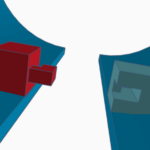
Closeup of a portion of the two cylinders. The left shows a small block attached to the inner wall with a square finger, while the right shows a small block with a cut out for the finger to fit into.

A Closeup of the Fastener Design, as Seen in TinkerCad

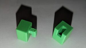
I probably could have reduced the failed attempts by measuring more carefully. To fasten the halves together, I first though of having a projecting shape on a small block on each side of one of the halves, and a matching cutout in a block on the inside of the other half. But I decided instead to use two fingers on one half, and matching slots on the other half. In hindsight, it might have been better to rotate the fasteners 90 degrees, so that the two halves didn’t get held in place against gravity just by friction, but it did work. If you make these yourself, the finger needs just a little bit of filing to fit snugly into the cutout and be held in place by friction.

A closeup of just the two fastener objects. The left has a cube with a square finger coming out one side, while the right is a cube with a cutout that the finger fits into.

A close-up photo of just the fastener objects. In the actual shades, they are integrated into the two shade halves and printed as one.

Printing and Building

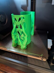
The shades are printed upside down, so that the partially closed top forms the base for printing. Because of the large overhangs for the cutouts, there are a fair num

A photo of one of the shades in the 3d printer while it prints. A large number of tree supports are visible.

One of the Shades Being Printed.

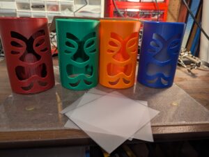
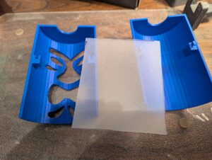
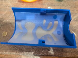
ber of supports needed. I used tree supports, as shown in the figure. Once the shades were printed, I cut out diffusers from sheets of frosted plastic. These were bent and placed inside the shades and held in place with three small drops of hot glue on the top and upper sides.

The front halves of four printed tiki heads, each a different color, with cut plastic diffuser sheets in front of them.

Printed Tiki Shades and the Cut Plastic Diffusers that will go Inside.

Close-up of the two halves of a blue shade with the diffuser sheet that will be mounted inside. The fasteners are clearly visible inside the two halves.

Close-up of One of the Tiki Shades and the Diffuser Sheet.

The inside front half of a blue tiki shade showing the shade curved around and inserted.

The Inside Front Half of a Shade, with the Diffuser Ready to be Glued in Place

Front exterior view of a blue Tiki shade, with the diffuser glued in place.

Diffuser Glued in Place


Results

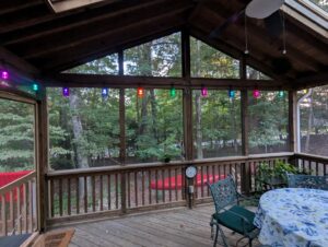
A view of the inside of the screened in deck, showing the eight tiki lights.

Set of Eight Finished and Installed

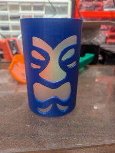
I’m quite happy with the results, and think that they look very nice, both in the daylight, when the different shade colors show up, and at night when they are lit. You can also print scaled down versions and put them over an LED candle. I did that with one of my test runs.

Blue tiki shade hung over one of the deck lights, with the light lit inside.

Finished and Installed Tiki Shade

Print Files

The print files for these shades are available on Thingiverse: https://www.thingiverse.com/thing:7154065