UPDATE: My setup changed between writing this and Halloween 2025. Updates and complete description, including revisions are in my later post.
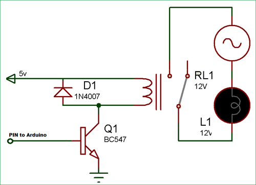
Next Halloween, my setup will include three coordinated skeletons performing together (probably doing “King Tut“). I want to use a single PIR motion detector to trigger three different props at different offsets from the original trigger. And some of the props can only speak or move for short amounts of time, so for a longer performance, they need to be repeatedly triggered. To do this, I have a PIR providing input to a Raspberry Pi Zero W. A python program running on the Pi then sends brief output trigger voltages individually to each of the props, according to the preset schedule for the routine. This same approach could easily be modified to trigger 2, 4, 5, or more coordinated props from a single start trigger. The hardware setup is very simple, and is shown in the figure.
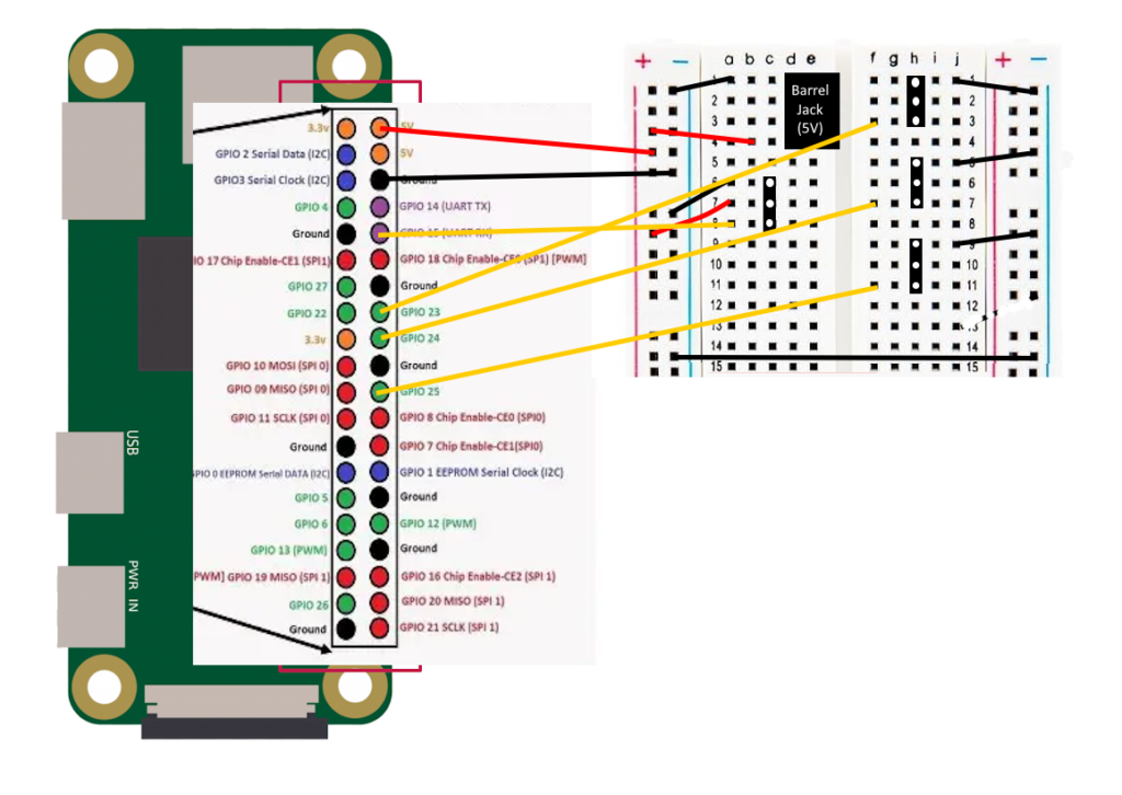
Power is provided via the barrel jack on the prototype board. This is also what powers the Pi. Their are four 3-pin female headers on the board. The one on the left is for the PIR sensor input. It has the power and ground connections, and the signal wire is an input that goes to GPIO pin 15 on the Pi. The other three headers are to go out to the three props. The grounds are connected so that the prop controls and this trigger share a common ground. The signal connections are outputs from GPIO pins 23, 24, and 25. There is no need for power for these connections.
In order to test the hardware, I rigged up one LED to each of the three signal outputs, put a resistor in to avoid burning out any of the LEDs, and linked the grounds. The test setup is shown below below:
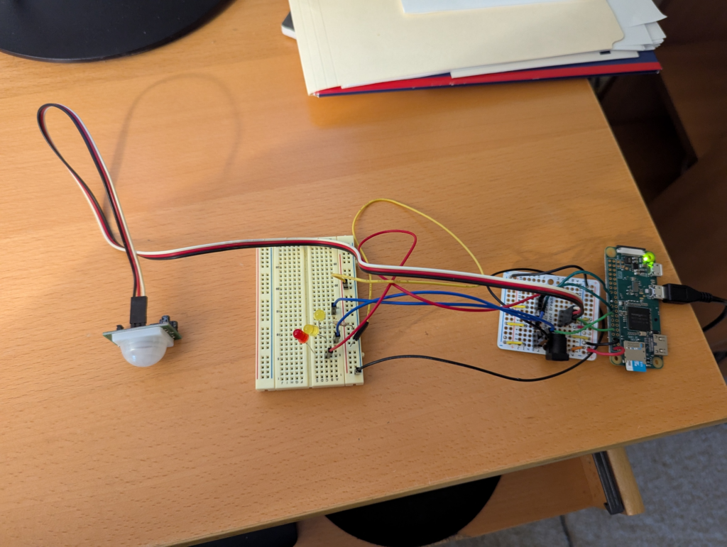
Test setup to make sure the hardware works and that I got the soldering correct.
I used the GPIO Zero library to write a simple test script for this test setup:
from gpiozero import LED
from gpiozero import MotionSensor

myLED1 = LED(23)
myLED2 = LED(24)
myLED3 = LED(25)
pir = MotionSensor(15)

while True:
    if pir.wait_for_motion():
        print("motion detected")
        myLED3.off()
        myLED1.blink(1)
        myLED2.blink(2)
        pir.wait_for_no_motion()
        print("no motion")
        myLED1.off()
        myLED2.off()
        myLED3.blink(3)
This has the pi wait until the PIR detects motion. Then it begins blinking the first 2 LEDs at different rates. When motion stops, those two LEDs are turned off and the third LED begins to blink. This cycle then repeats until the user hits CTRL-C to stop the test script.
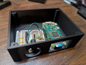
Completed electronics in project box
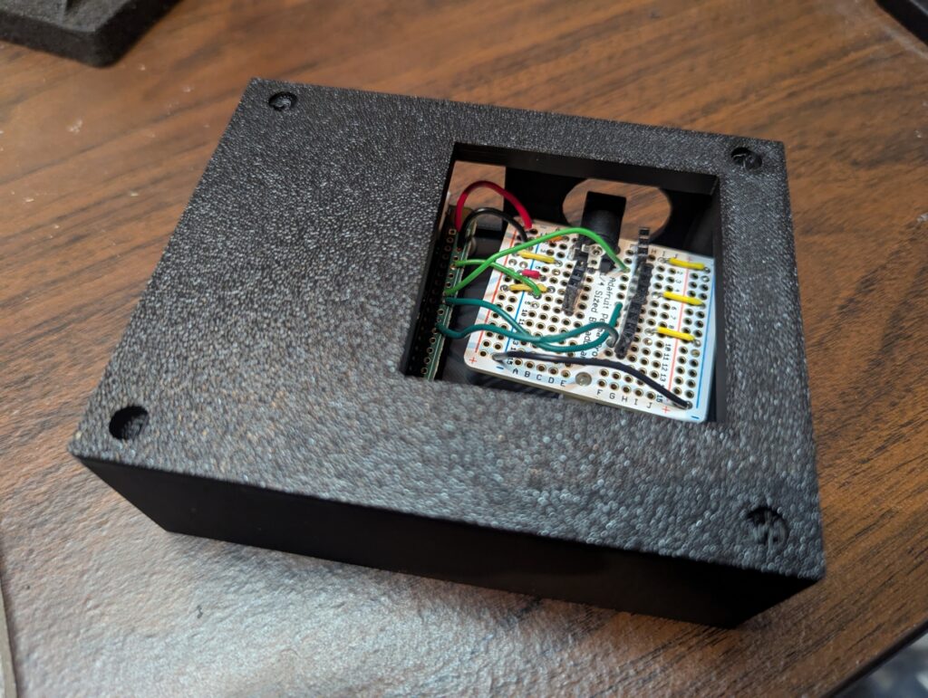
Completed project box with electronics inside and lid on the top
The circuit is mounted in a custom 3d printed project box with slots for the power, sensor, and output wires, as well as a slot for accessing the Pi’s micro SD card. I designed the box using TinkerCad. I also 3d printed the standoffs, and just used hot glue to glue the Pi and the breadboard in place. I put in large holes so that it would be easy to plug and unplug the connectors and also get my fingers in to insert or remove the micro SD card. The top has a large cutout to make it easy to access the 3-pin headers. The finished hardware is shown in the figures on the right.