
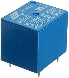
A Relay
Today’s blog is on a simple topic, but one that comes up a lot, and may be of use, especially to beginners. Many projects involve controlling a higher voltage device or devices based on an external event triggered by a sensor, such as a PIR. And to control the higher voltage device, a relay is used. Along with the relay, you’ll need a transistor to provide adequate current to drive the relay, a diode to protect from reverse currents when the relay switches off, and probably a resistor to limit the current draw. This is simple enough, but another option is to use a relay module. The module combines a relay along with these other components into one simple package.
Depending upon your application, you may also put some sort of timer circuit, or a microcontroller such as an Arduino, or a single board computer (SBC) like a Raspberry Pi between the sensor output and the relay input. This lets you implement more complex logic than simply having the relay echo the output from the sensor. For example, one could have a light toggle on or off each time the sensor is triggered. Or, when triggered, one could have a device stay on for a set amount of time before turning off. Or even more complex actions. But if you don’t need the added logic, you can use the sensor directly, without a microcontroller or SBC.
The output voltage from the sensor or controller board must be high enough to trigger the relay, but voltage alone is not enough. The driving device must also be capable of supplying enough current. This is often not the case for either sensors or computer boards. They lack the power to drive many relays.
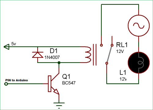
Relay and Driver Circuit
The solution is to use a transistor. The sensor or board switches on and off the larger current flow through the transistor, and this, in turn, drives the relay. In addition, one needs a resistor to limit the current drawn from the sensor or controller and a “flyback” diode to protect both devices and the transistor from reverse currents when the relay turns off. This is shown in the figure, taken from Circuit Digest’s Arduino Relay Control Tutorial.
You can learn more about a relay and the relay driver circuit in the article How Electrical Relays Work at Circuit Basics.
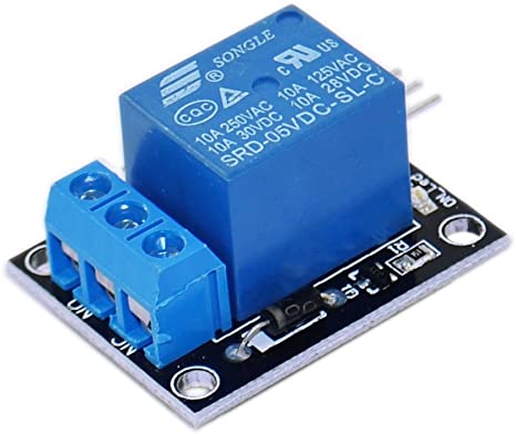
Relay Module
But rather than using discrete components, there’s another option which is often quicker and easier: the relay module. A relay module combines all of these elements into a single board. It may include additional features, such as an LED to indicate when the relay is triggered. In this way, you only need your sensor, optionally a controller for more complex logic, and the relay module. No discreet diodes, transistors, or resistors required. I’m using the one discussed in this article, along with a PIR sensor, to trigger the “Try Me” switch on a Halloween prop. Although the signal output for the PIR is 3.3V and the relay is a 5V input signal relay, it seems to work just fine. As you can see, it’s the same relay, mounted onto a circuit board along with the transistor, resistor, diode, and indicator LED. In addition, the signal side inputs are connected to 3 male pins for easier connections. The pins are spaced so that they will fit into a standard breadboard or for connecting a standard 3-wire servo cable.
So the next time you need to trigger a higher voltage AC or DC device, reach for a relay module.