I like tiki / exotica music, visiting good tiki bars, and interesting tiki drinks. Recently, we were on vacation in Montreal and visited the Snowbird Tiki Bar. When we were there and looking at the decor, my wife suggested that I make some tiki covers for some of the lights on our deck. Challenge accepted!
Design
In order to build the tiki shades, I needed a 3d design. The basic concept began with a hollow cylinder with the tiki head design cut as holes in one side. I used TinkerCad to do the bulk of the design work. The shades had to fit around and over the deck lights, which are permanently attached to their cord, and the bulbs can’t be removed. So I needed the shades to be in two pieces that would fit around each light. I also needed a top with an opening large enough to let the cord through, but small enough so that the shade stayed on and didn’t simply fall down off the light. Finally, I needed a way to fasten the two halves of the cylinder together around each light.

The .png File for the Face
I first found a photograph online of a tiki light that I liked. From that I edited it a bit and the result was a mask as a .png file. The idea is to use the design to generate the set of holes to cut into the hollow cylinder, rather than try to hand-draw and cut out the holes. You can import a design such as this into TinkerCad and turn it into a 3D object provided it is in SVG format, not a jpeg or png. So I used the free online SVGCreator to turn the png file into an svg. Then I simply imported the svg file into TinkerCad.
It took a couple of trial and error attempts to get the top the right size.
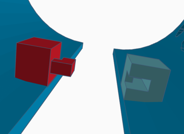
A Closeup of the Fastener Design, as Seen in TinkerCad
I probably could have reduced the failed attempts by measuring more carefully. To fasten the halves together, I first though of having a projecting shape on a small block on each side of one of the halves, and a matching cutout in a block on the inside of the other half. But I decided instead to use two fingers on one half, and matching slots on the other half. In hindsight, it might have been better to rotate the fasteners 90 degrees, so that the two halves didn’t get held in place against gravity just by friction, but it did work. If you make these yourself, the finger needs just a little bit of filing to fit snugly into the cutout and be held in place by friction.
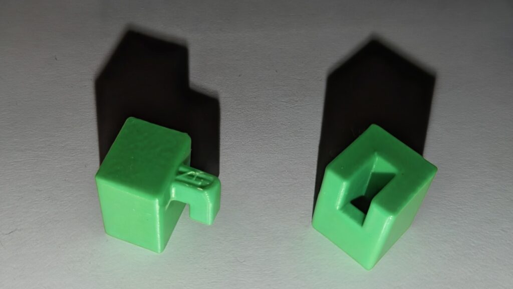
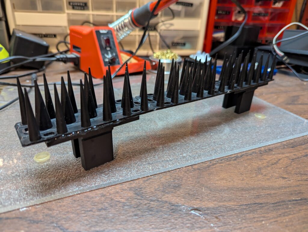
A close-up photo of just the fastener objects. In the actual shades, they are integrated into the two shade halves and printed as one.
Printing and Building
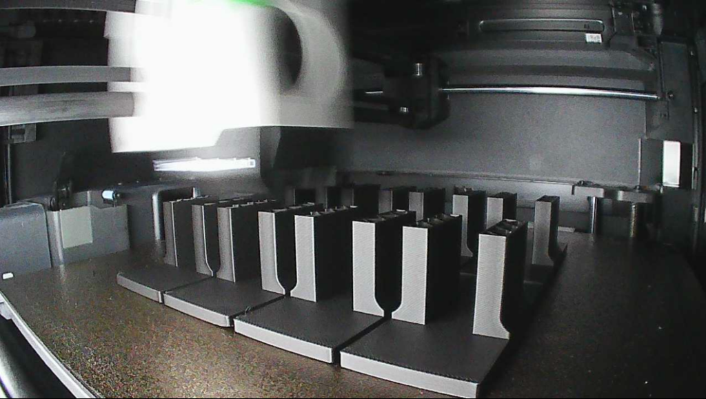
The shades are printed upside down, so that the partially closed top forms the base for printing. Because of the large overhangs for the cutouts, there are a fair num
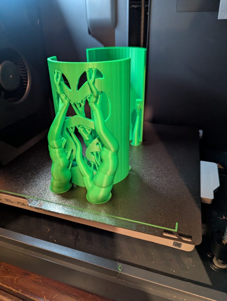
One of the Shades Being Printed.
ber of supports needed. I used tree supports, as shown in the figure. Once the shades were printed, I cut out diffusers from sheets of frosted plastic. These were bent and placed inside the shades and held in place with three small drops of hot glue on the top and upper sides.
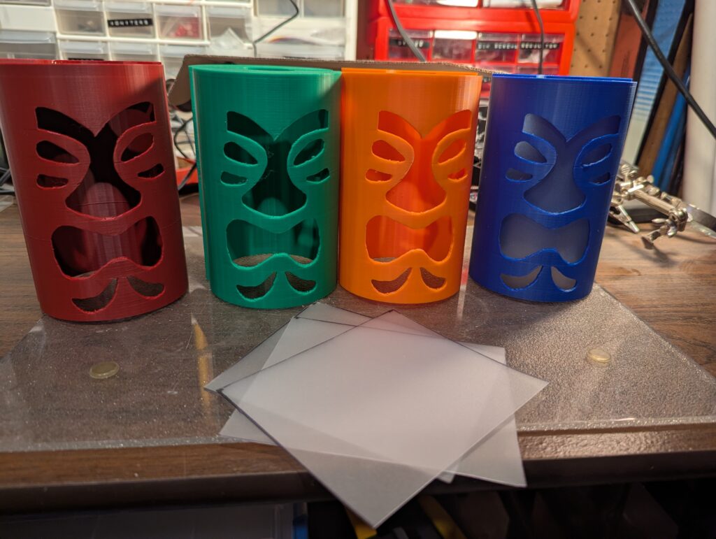
Printed Tiki Shades and the Cut Plastic Diffusers that will go Inside.
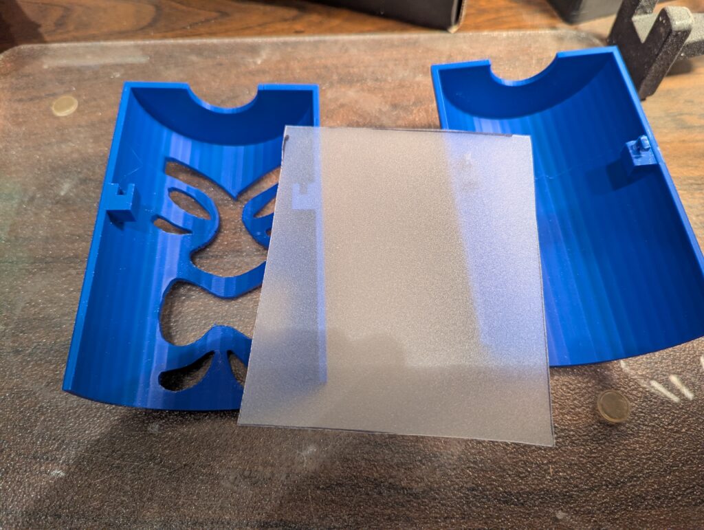
Close-up of One of the Tiki Shades and the Diffuser Sheet.
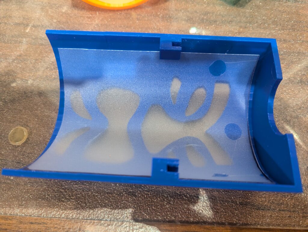
The Inside Front Half of a Shade, with the Diffuser Ready to be Glued in Place
Diffuser Glued in Place
Results
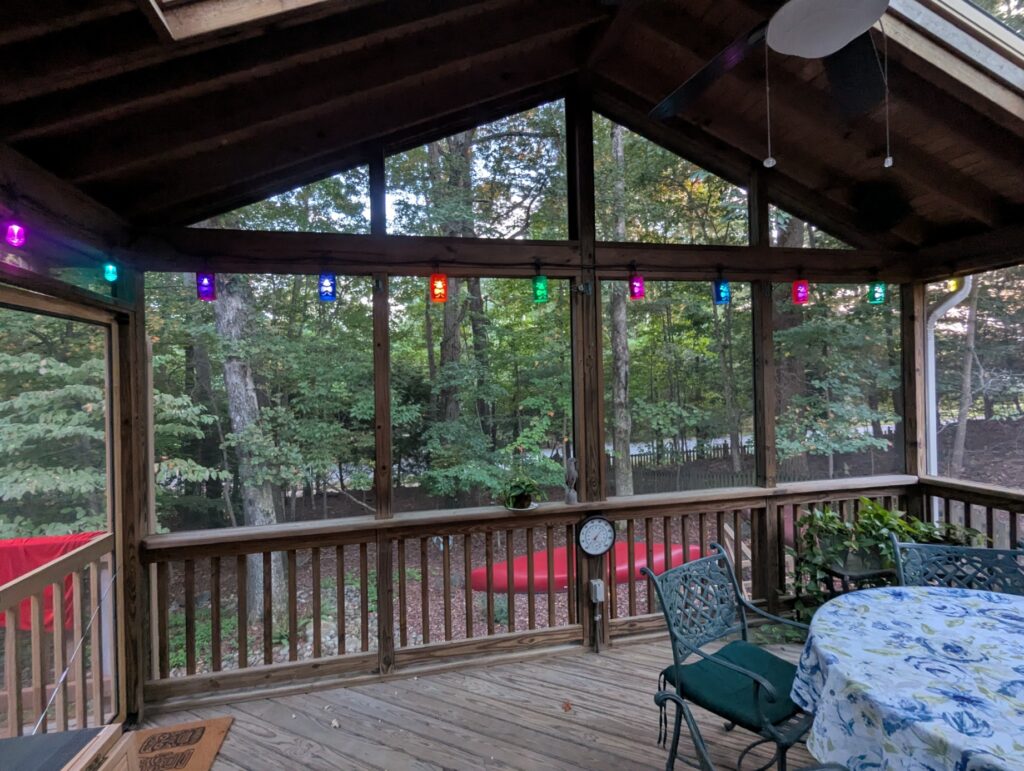
Set of Eight Finished and Installed
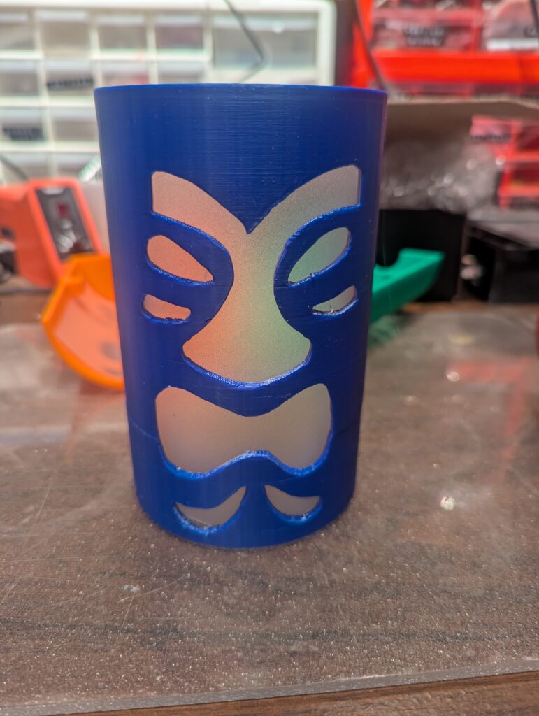
I’m quite happy with the results, and think that they look very nice, both in the daylight, when the different shade colors show up, and at night when they are lit. You can also print scaled down versions and put them over an LED candle. I did that with one of my test runs.
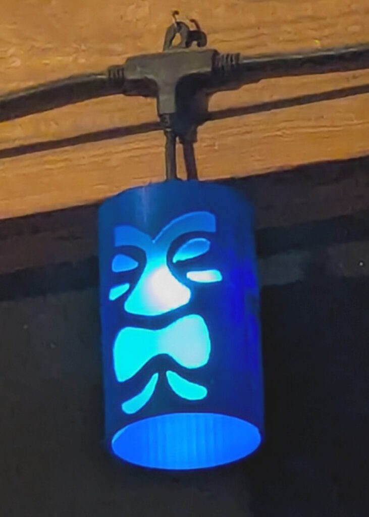
Finished and Installed Tiki Shade
Print Files
The print files for these shades are available on Thingiverse: https://www.thingiverse.com/thing:7154065