Pi-based multi-prop trigger for animatronics, Part 2

Back in March I wrote about a Pi-based controller for multiple Halloween props. As I go the props ready this year, I realized three things: 1) I wanted to change the routine from what I planned, 2) The way I needed to connect this particular set of props was different than what I’d been planning and 3) it turns out I couldn’t use an electromechanical relay board to react to the trigger signal from the Pi to one of the skeletons, because it holds open too long. So, back to the drawing board, as well as desoldering and resoldering.

My setup for this year includes two skeletons talking to one another. One is a simple talking pose-and-stay type of skeleton, with light up eyes and a moving jaw driven by a motor. The other is a talking and moving skeleton prop called Grim. Besides wanting movement to trigger them, I needed to be able to provided custom audio phrases for them to say to one another.

Talking Skeleton

The talking skeleton [insert photo] uses a motor to drive the jaw movement, and has light up LED eyes. In order to allow for custom audio, I disconnected the built in sensor and sounds and connected a commercial audio controller called a Jemmy Talk. The Gemmy Talk takes line level audio input and sends out voltages to move the motor. It also has a pass through for the audio, so that you can send line level output to an amplifier. I don’t use this latter feature in my set up. I use a DFPlayer MP3 player as my audio source. It has both a line level output, which I feed to the Jemmy Talk, and amplified audio that I feed directly to the speaker built into the skeleton. The board with the DFPlayer is also where the power is supplied, through a barrel jack connector to a 5V supply. The button switch on the board is to test things without requiring an external trigger signal. The two 3-pin connectors on the board are not used. The three boards are shown in the picture. Besides the Jemmy Talk and the board with the DFPlayer, the third board receives the triggers from a Raspberry Pi (see “Controller,” below).

Picture showing the audio source and controls for the skeleton, showing the Jemmy Talk board, the board with the DFPlayer MP3 player, and the board with input from an external controller and Darlington array. All are wired together as they are when in use.

The audio source and controls for the skeleton, showing the Jemmy Talk board, the board with the DFPlayer MP3 player, and the board with input from an external controller and Darlington array.

The circuit board on the bottom will receive the triggers from a Raspberry Pi (not shown) and features a Darlington ULN2003 transistor array chip that acts as a set of relays to signal the DFPlayer to play the audio and also to turn the skeleton’s eyes on. I had originally used an electro-mechanical relay rather than the Darlington array, but the MP3 player requires that the button press to play the audio be short, and the relay held closed too long when triggered. The MP3 player uses a short drop to ground to signal to play the next track, which is what I needed, while a longer drop on the same pin signals the player to turn up the volume. Had I known that I would be using the Darlington array from the start, rather than a separate relay board, I could have fit everything on just one, rather than two, boards.

If the skeleton was like many, with simple LED eyes, I could have used the Jemmy Talk to control them as well, but it doesn’t. So I kept the Try Me wires connected to trigger the eyes to go on. That is what the second trigger on the Darlington is for. That means that I needed two signals from the Pi, one to turn on the audio and one to light the eyes, but this gives me more flexibility for the future. Here’s a picture of the final circuits in a small project box I printed for the project:

Grim

The Grim prop was modified by adding a Grim Talker board from the same source as the Jemmy Talk. Once that was installed per the directions, I just needed to put the correct new audio file on the SD card that goes into the Grim Talker (no external MP3 player needed) and determine how to trigger it. It can be triggered to activate by either the sensor built into the original Grim prop, by cycling the power on and off, or by a Try Me button switch connected through a 1/8″ MONO cable jack. When triggered, the audio and motion routine starts. The audio will play through completion, but the motion will stop once it’s routine (about 30 seconds) ends. If the audio is longer (as in my case) and you retrigger the prop before the audio ends, the motion will start up again. This is what I wanted to do.

Cycling the power wouldn’t do what I wanted, as it would kill the audio. I didn’t want to mess with the built in PIR sensor, as I may want to use it in the future. And I needed to coordinate Grim with the other skeleton. So that left the try me switch. So the multi-prop controller that I put together (a modification of what I described in the Pi-based controller for multiple Halloween props write-up, uses another Darlington to act as a switch that closes to trigger the prop.

Controller

Pictorial diagram of the controller. PI on the left has connections to the other board for power, one connector to a 3 pin female header on the other board for input from a PIR, and four GPIO output connections (one to a 3 pin header for a PIR type of controlled prop, two to a 3-pin connector for either a PIR control or one needing two separate signal inputs, and one that goes to the input of a ULN2003 Darlington on the board, which is connected to close a connection when triggered.

Raspberry Pi based multi-prop controller

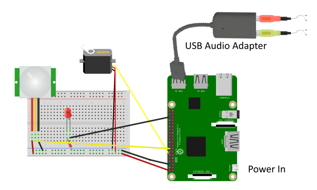
In order to control multiple, coordinated, props from a single motion sensor, I put together a simple circuit that controls up to three props, of a couple of different types. A PIR provides input to the Raspberry Pi, which then sends output signals for up to three props. One output simply closes a switch, and it is good for triggering props through their “try me” button wires (replacing the button / switch). For this, the trigger output from one of the GPIO pins on the Pi triggers a relay in a Darlington. This is a bit of an overkill, as I’m only using one of the eight channels on the Darlington, but it’s cheap, easy to use, and works.

Another GPIO pin sends and output voltage to the sensor wire in a 3 pin servo connector. The grounds also link the prop to the controller to provide a common ground. This works for any prop set up to look for input from a PIR or similar sensor providing a positive low voltage signal. What would normally be the voltage source on a servo connector is left unconnected, as it’s not needed to power anything.

Finally, two other GPIO pins send output to another 3-pin connector, using what would normally be the signal and voltage lines on a servo connector. This is for the talking skeleton as described above, with one signal to start the MP3 audio player and the other to control the eyes. Again, the ground is connected to ensure a common ground. This connector could also be used to simply control a prop that only needs a single signal, rather than two, providing flexibility.

The python controller program for this year is really quite simple:

from gpiozero import DigitalOutputDevice
from gpiozero import MotionSensor
import time

skel_talk = DigitalOutputDevice(23)
skel_try_me = DigitalOutputDevice(24)
grim_trigger = DigitalOutputDevice(25)
pir = MotionSensor(15)

while True:
    pir.wait_for_motion()
    print("motion detected")
    skel_talk.on()
    skel_try_me.on()
    grim_trigger.on()
    time.sleep(0.2)
    skel_talk.off()
    skel_try_me.off()
    grim_trigger.off()
    time.sleep(30)
    print("waited 30 seconds")
    grim_trigger.on()
    time.sleep(0.2)
    grim_trigger.off()
    time.sleep(50)
    print("ready to trigger again")

The program uses the gpiozero library for interfacing with the Pi’s GPIO pins. Three pins are used for outputting signals: named skel_talk to trigger the skeleton’s audio, skel_try_me to trigger the relay to close the skeleton’s try me connection, and grim_trigger to send a trigger signal to the Grim prop. These are all defined as simple DigitalOutpuDevice pins. There is one input pin, named pir, which is defined as a MotionSensor input.

The program is an endless loop which waits for the PIR sensor to be set off. When that happens, the three output triggers are both set high (True) for 0.2 seconds and then set back off. Then the program sleeps for 30 seconds while the Grim motion is running, then the grim_trigger is again set high again for 0.2 seconds to trigger the motion to restart (the audio, which is about 1 minute long, is still running). Finally, the program waits 50 seconds. The audio and motion will continue for approximately 30 of these seconds, with the additional 20 seconds being a dead time so that the props don’t immediately retrigger. The print statements are there simply for initial debugging. I used Crontab to set the script to autorun in the background upon startup. I need to modify the script so that once triggered, it also periodically closes the try me switch on the talking skeleton. At present, the eyes only light for a short time at the start of the dialog.

Results

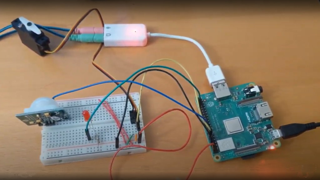
Here’s the two circuits, in their circuit boxes, and then a video

Photo of the electronics for the skeleton in one project box and the pi-based multi-prop controller in a second project box. The skeleton controller has a Jemmy Talk circuit board, a board with the MP3 player, and a third board. The prop controller has a raspberry pi and a board with a Darlington array, source for power, and several female 3-pin headers.

The electronics for the talking skeleton on the left and the Pi-based multi-prop controller on the right.

of the final result in operation. Unfortunately, it’s not a great video clip, but it does show the two skeleton props talking back and forth in a short excerpt from their longer dialog. An mentioned above, I need to add a line or two to the script to periodically retrigger the eyes of the smaller skeleton, so that they stay lit during the whole dialog.

It took more effort than I originally thought it would, partly due to faulty planning on my part, but I think it all came together nicely.

Wireless Microphone Using Two Raspberry Pi’s (Updated 5/4/2021)

I’m in the process of integrating wireless audio input and  into my Yorick the Mimic project. This involves adding microphone input and wireless transmission into the sensor cap and then integrating the movement controller with a modified version of Chatter Pi that takes the transmitted audio as an input.

In order to get started, I first put together bare bones transmitter and receive programs. I’m using Python, along with PyAudio, which I also used in Chatter Pi, to process the audio on both ends. I’m using UDP to send the data packets contain the audio. I saw some examples using TCP, but it seemed to me that UDP was better suited to real-time audio. If anyone knows more on which is the better approach, please post a comment.

PyAudio

The code runs fine, but generates a continuing stream of

ALSA lib pcm.c:8424:(snd_pcm_recover) underrun occurred

warning messages. This doesn’t interfere with the program’s operations, but if anyone knows why I’m getting them and/or how to eliminate the warnings, I’d appreciate your letting me know.

PyAudio has two modes, a blocking mode, where each call to pyaudio.Stream.write() or pyaudio.Stream.read() blocks until all the given/requested frames have been played/recorded and a non-blocking mode where a callback function is launched in a separate thread, so that processing can continue in the program calling it, and the thread ends when the current chunk of audio is processed. The gist with my code uses the non-blocking mode using the callback function and two different versions of the receiver, one using blocking mode and one using non-blocking. You need to be careful when using the non-blocking mode that the callback function does not include anything really time consuming, like file reading and writing. If it does, it can’t finish before the next chunk of audio is ready and you get clipping or worse problems.

As is well-known, the audio jack output on a Pi produces low volume, poor quality audio. A USB speaker works much better. However at least for the speaker I’m using, I need to use the ALSAMixer to control the volume. If I touch the speaker icon in the GUI, it produces no sound if set to anything other than the maximum volume. Again, if anyone knows why and how to fix this, please add a comment.

By design, both the xmit and rcv programs run forever once started. There’s one other feature beyond the bare bones basics. The receive program has a Boolean variable named EFFECTS. If set to True, the Sox library is used to deepen the pitch and add a bit of reverb before sending the audio to the speaker.

Hopefully this project will help others with similar needs.

Further UPDATED for Halloween 2021! ChatterPi: a Raspberry Pi Audio Servo Controller for Talking Skulls

Introduction

ChatterPi is a software package that turns a Raspberry Pi into an audio servo controller. In other words, the Pi outputs commands to control a servo based on the volume of the audio input. The input can be either stored audio files (in either mono or stereo .wav format) or from an external source, such as a microphone or line level input. One of the uses is to drive animatronic props, such as a skull or a talking bird.

[This post has been updated to reflect new features added in the latest version]

Background: A Brief History of Talking Skull Control

A common prop that still makes a good impact is a talking object, whether a skull or animal. Some lower cost commercial props use a motor and spring. Another approach is to pre-program a complete sequence to match the vocals, but this is very time consuming and if you want to change the vocals, or even just edit them slightly, you need to reprogram the entire sequence. For that reason, the use of an audio servo controller to drive a servomotor controlling the jaw is a very popular approach. There are several variations. One of the earliest use hardware to detect when the audio exceeded a threshold, and then began moving the jaw towards a fully open position, and when the audio went below the threshold, it would begin closing the jaw. “Scary Terry” Simmons may have been the first to develop an electronic hardware board to do this, and Cowlacious Designs has continued to improve and sell commercial versions, with many added features such as a built in audio player, various triggering options, and the ability to control LEDs as eyes.

Later, someone named Mike (no relation) combined an Arduino with a hardware volume level board to produce the Jawduino. This went from having just 2 levels to 4. The original project just took audio in and controlled the servo, but others added extensions to play stored mp3 files and/or randomly move additional servos (for example, http://batbuddy.org/resources/Halloweenstuff/TalkingSkull.php).

A few years ago, Steve Bjork from Haunt Hackers combined dedicated hardware with a propeller microcontroller to increase the number of levels to almost 256 and also to filter out low and high frequencies that don’t tend to result in jaw movement for spoken sound. The result is the Wee Little Talker. This commercial board also has an onboard mp3 player, can be triggered externally, control LED ‘eyes,” and adds a wide array of features including a voice feedback menu system.

It occurred to me that with current single board computer capabilities and powerful software libraries, it should be possible to incorporate most of the best features of all of these into a single, software-based system running on a Raspberry Pi. The result is ChatterPi. ChatterPi was developed from scratch using the Python language, but ideas for capabilities and features were freely borrowed from previous audio servo controller projects.

Features

ChatterPI is designed to be extremely powerful and flexible without requiring the user to modify any of the code (although advanced users can certainly do that as well). Table 1 compares the current capabilities of ChatterPi with other audio servo controllers. The full range of capabilities and options are described in the Operations subsection.

Table 1. Feature comparison of ChatterPi and other audio servo controllers

Table comparing features of Chatter Pi to other audio servo controllersDemonstration Video

This video shows ChatterPi in action, using both a saved .wav file and microphone input. ChatterPi is controlling the jaw movement. The other skull movements are pre-programmed as a script running on a Pololu Maestro Servo Controller.

Using ChatterPi

This section describes how to set up and install both the hardware and software for using ChatterPi, and for using it.

Hardware

ChatterPi was developed and tested on a Pi 3 A+ and a Pi Zero W. It should work on any Pi except Pi 5’s. Originally it ran too slowly on a Pi Zero. A section of code for analyzing audio volume used list processing and a loop. This code was replaced using Numpy, and it’s now fast enough to work on a Pi Zero. The GPIO hardware / firmware was changed on the Pi 5, and the underlying library that I use isn’t compatible. I may or may not update this in the future.

In addition to the Raspberry Pi, you’ll ]need a USB sound card. This is needed for several reasons. First, if you plan to use an external sound source, you need a way to get audio into your Pi. Second, besides not producing very good sound, the audio out connector may share timing with the Pulse Width Modulation (PWM) code that is needed to drive the servo, creating conflicts.  Use of an inexpensive USB sound card solves both issues. I’ve used one from Adafruit that sells for less than $5 and works well (see https://www.adafruit.com/product/1475). You will need TRS (standard stereo) plugs or an adapter to go into the headphone and microphone jacks on the sound card. The card does not work with a TRRS (combination microphone / stereo headphone plug. You only need a microphone or other external sound source if you wish to use one. Otherwise you can use audio .wav files that you save on the Raspberry Pi. You still need the USB sound card for audio output, however.

That’s all you need for the audio servo controller. Of course, you’ll need a power supply and a servo that you want to control, such as a servo-equipped talking skull, and a passive infrared sensor (PIR) if you want to trigger your prop using one. I used this one (https://www.parallax.com/product/555-28027) from Parallax for development, as I had a spare one already. ChatterPi can also be set to trigger off of a repeating timer or to just turn on and run if you don’t want to use an external sensor.

Figure 1 shows a test bench setup for testing operation. The Red LED is attached to the “TRIGGER_OUT” pin for testing purposes. It can be moved or another LED and resistor attached to the “EYES_PIN” to test that feature. The TRIGGER_OUT pin goes high for 0.5 seconds when the controller is triggered. This can be used to trigger another prop or controller. The EYES_PIN stays high for as long as the audio plays.

Figure 1. A layout for fully testing the ChatterPi

The default PIN selection (which can be changed in the config.ini file) are:

  • Jaw servo: 18
  • PIR input trigger: 23
  • Trigger out: 16
  • Eyes: 25

Figure 2 is a photograph of my test setup. The placement of the wiring on the breadboard is slightly different because I was using it to test a variety of items and also a 3-wire servo controller wire, but the schematic connections are identical.

picture of the test setup

Figure 2. A picture of the test seup used for development

Software Overview

Knowledge or understanding of the software code is not required to operate or use the ChatterPi. The ChatterPi package consists of eight Python 3 modules and one configuration file, as shown in Figure 3.

The configuration file, config.ini, holds all of the user selectable parameters, including which pins are used for which functions, whether the audio source is the microphone input or stored .wav files, which servo control mode should be used, and the servo threshold levels. The config.py program simply reads these values and makes them available in memory during runtime.

The main.py program essentially simply loads the configuration parameters on start-up and calls control.py.  The functions in control.py are not folded into main.py in order to avoid a submodule having to import the main program, which can be problematics.

Most of the processing occurs in the control.py and audio.py modules. The control.py program handles most of the triggering (either a timer, an external trigger such as a PIR, or immediately upon startup, with the method specified in the config.ini file. It uses the GPIO Zero and PiGPIO libraries to monitor the triggering sensor and send output to the output trigger and led pins. PiGPIO is used as the GPIO layer underneath GPIO Zero because it uses DMA control for the Pulse Width Modulation (PWM) control used to the control the servo. Some other libraries, including the default one used by GPIO Zero, use software PWM, which is adequate for tasks such as controlling the brightness of LEDs, but not precise enough for servo control.

Unless the triggering mode is START, the file enters an infinite loop waiting for either a timer to expire (TIMER mode) or the external trigger to be generated (PIR mode). The wait functions meet the requirements and during development, interrupt driven approaches interfered with the audio output, probably due to timing conflicts. In TIMER mode, the timer is restarted after either the audio file finishes playing (if the source is FILES) or after a configurable pre-set time (if the source is MICROPHONE).

When triggered, an event handler is called that, depending upon the settings, sets off the TRIGGER_OUT to trigger another prop or device and turns on the LED eyes or other low power device. Then, if the audio source is FILES, it will call tracks.py, which will select the next .wav file to be played and call audio.py, passing the name of the .wav file to be played. If the audio source is MICROPHONE, audio.py is called without passing a file name.  When the call to audio.py returns, the event handler turns the LED eyes off and returns.

Audio playback, audio analysis, and servo control are all performed by the audio.py module. It defines one class, AUDIO. When the audio.play function is called, it checks on whether the audio source is MICROPHONE or FILES and opens a PyAudio stream appropriately. The stream call runs in a separate thread (this is automatically handled by PyAudio). For each chunk of the input stream, a callback function is called. This callback function is where the audio stream volume is analyzed. The average volume for each chunk is calculated, and the servo is commanded to the appropriate position based on that average volume and the threshold levels that the user has specified in the config file. The wave library is used to read the wave files from storage, and the struct library is used to help deconstruct the wave data to calculate volume and to help to separately analyze the left and right channels for stereo files. The number of levels, the specific thresholds, and whether a bandpass filter is applied before calculating the volume is based on the STYLE setting set by the user in the config file. In addition to the official documentation, I found a slide presentation, Introduction to PyAudio, by Jean Cruypenynck to be very helpful.

If the STYLE is set to 2, then bandpassFilter.py is called to process the digital audio stream and return a modified stream with the bandpass filter applied. The program is very short and simple. It uses two functions from the scipy signal processing library to filter out audio input below 500 Hz and over 2500 Hz. No bandpass filter is applied for STYLE 0 or STYLE 1.

When AMBIENT is set to ON, the ambient playback function in audio.py must also monitor for triggering events (either the timer or sensor), since it needs to interrupt itself and pass control back to control.py when such an event occurs.

The config.ini file can either be edited directly or through a GUI program named controlPanel.py. If the servo or controller subset of parameters are changed during execution, the changes will be reflected the next time a vocal track is triggered. Other changes will not take effect until after ChatterPi is stopped and then restarted.

maxVol.py is a utility program that can be launched from the control panel. It reads and analyzes each wave file in either the vocals or ambient subdirectories and writes them back with the volume levels increased to the maximum possible without clipping or distortion.

Screenshot of Chatter Pi Configuration Control Panel

Screenshot of Chatter Pi Configuration Control Panel

Software Installation, Setup, and Operations.

See the User’s Manual on GitHub for complete instructions. UPDATE: In addition to the source code, there’s now a Pi SD card image file available for download, so you won’t have to do any installations of dependencies or the source code, just install the image on a micro SD card, load it up in your Pi, and your ready to go! See the link in the README file at GitHub – ViennaMike/ChatterPi.

Project Roadmap

This version, 0.9, includes all the features currently planned for ChatterPi. That said, there are two additional features that might be added at a later time (or if anyone cares to add them to this open source project:

  • The ability to use .mp3 files. Simply playing MP3 files on a Raspberry Pi is easy, but they must be processed in real-time as a stream to drive the servo controller.
  • Add drop down pick lists for many of the options in the control panel, and allow lower case values to be entered, auto-correcting to upper case.
  • Add the ability to start and stop the execution of ChatterPi from the control panel.

Wrap Up

The code is open source and published on GitHub (https://github.com/ViennaMike/ChatterPi), and I would welcome anyone who wanted to work on adding any of these advanced features.

To report a bug, make a suggestion, or ask a question, please go to the GitHub repository for the project (https://github.com/ViennaMike/ChatterPi) and open an Issue. To do so, first click on the issues tab, and then use the green “New Issue” button. It’s a good idea to first browse through or search other reported issues to see if someone has already reported the same issue or asked the same question. You can then add comments or suggestions to existing issues, rather than opening a new, duplicative issue.