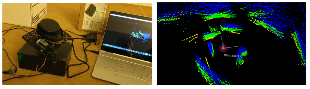
Lidar setup and 3D scan
It’s been over two years since I first wrote about lidar units, and at the time I stated I wrote that the final part would be a look at the Neato XV-11 that I had purchased off of Ebay. That got delayed by several years, first due to an initially bad unit (but great response from the seller to correct the problem!), then higher priority projects and life intervened, but I’m finally ready to report. Besides playing around with the unit, I added some enhancements to the display software available from Surreal, who make the controller unit I used, and mounted the lidar on an pan-tilt system so I could do 3D scans.
Equipment:
- Neato XV-11 lidar unit (originally used in Neato robotic vacuum cleaners, check ebay)
- Surreal XV Lidar Controller v1.2
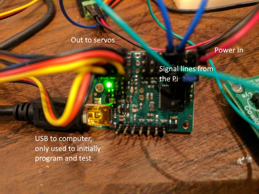
- Pololu Micro Master 6 Servo Controller
- Lynxmotion Micro Pan and Tilt Kit with Servos
Construction
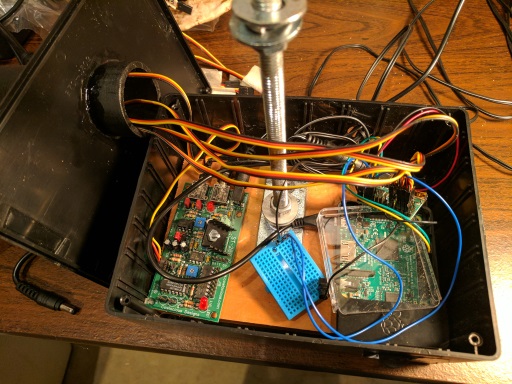
Construction is really straight-forward. I mounted the lidar to a plastic base plate using some standoffs (since the drive motor sticks out underneath the unit). Then I mounted the base plate to the pan-tilt system, and mounted that to a project box I had lying around.

XV-11 lidar mounted on a servo-controlled pan/tilt system for 3D scans
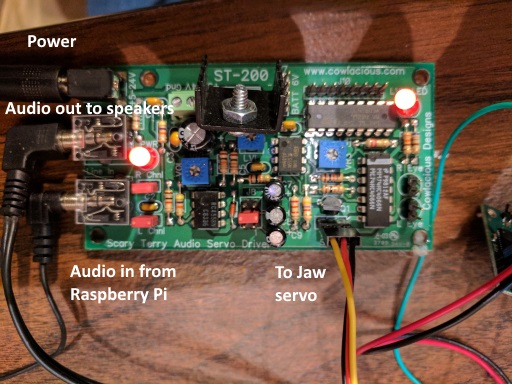
The XV Lidar Controller version I used is built around a Teensy 2.0 and uses PID to monitor and control the rotation speed of the Lidar, controlling it with PWM. In addition, it reads the data coming off the lidar unit and makes the information available through a USB port.
The servos are both connected to the servo controller, which also uses an USB interface. The figure below shows the setup:
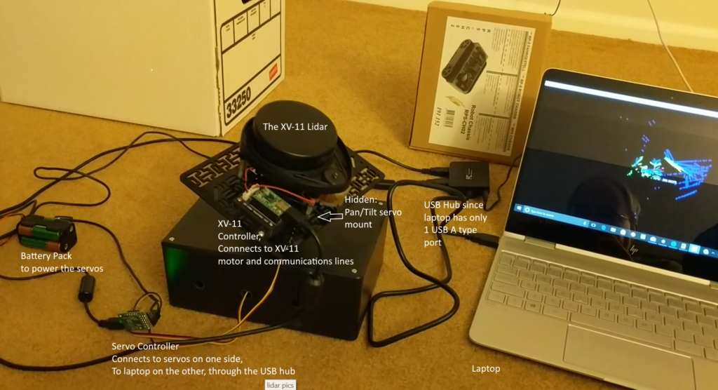
Labeled picture of the setup
Software
I didn’t touch the firmware for the lidar controller. The source code is available through links at Surreal’s site. There are several very similar versions of visualization code in python that takes the output from the lidar controller and displays it using VPython. They all seem to start from code from Nicolas Saugnier (Xevel). I started with one of those variants. The main changes I made were 1) to add the ability to do a 3D scan by sweeping a pan/tilt mount through various pre-set pan and tilt angles and 2) to add the ability to capture and store the point cloud data for future use. In addition, I wrote a routine to then open and display the captured data using a similar interface. Additional smaller changes were made such as implementing several additional user controls and moving from the thread to the threading module.
The pan-tilt setup does not rotate the lidar around the centerpoint of itself. Therefore, in order to calculate the coordinate transformation from the lidar frame of reference to the original non-moving frame you have to do both a coordinate rotation and an angle-dependent translation of the origin. This is handled by the rotation.py routine using a rotation matrix and offset adjustments.
The servos are controlled through a servo controller, with the controlling software (altMaestro.py) being an enhanced version of the python control software available through Pololu that was originally developed by Juhapekka Piiroinen and Brian Wu. My version corrects some comments which were inconsistent with actual implementation, fixed bugs in the set_speed routine, and added “is_moving” as a API interface to be able to check whether or not each individual servo was moving.
The point cloud data is stored in a simple csv file with column headings. Each row has the x, y, and z coordinates, as well as the intensity value for the returned data point (provided by the XV-11), and a flag that is set to 1 if the XV-11 has declared that the intensity is lower than would normally be expected given the range.
When displaying the results, either during a scan or from a file, the user can select to color code the display by intensity, by height of the point (the z value), or by neither. In the latter case, points with the warning flag set are shown in red. In addition, as in the original software, the user can toggle showing lines from the lidar out to each data point and also an outer line connecting the points.
The software, along with some sample point cloud files, can be found on my Neato-XV-Lidar-Tools repository on GitHub.
A Note on VPython Versions
The original visualization code was written for Python 2.x and for VPython 2.6 or earlier. After some deliberation, I decided not to update this. Post version 6, VPython internals have been entirely redone, with some minor changes to how things are coded. However VPython 7 currently has issues with Spyder, that I use as my development environment, while VPython 6 won’t run in Python 3.x, and never will. It shouldn’t be a hard lift to convert the code, but note that if you update it to run under Python 3 you’ll also need to update to VPython 7 or later, while updating VPython alone may create issues depending upon your development environment. So it’s best to make both updates at the same time.
Sample Results
This first scan is a 2D scan from the floor of my kitchen, with annotation added. It clearly shows the walls and cabinets, as well as the doorways. Note that the 2nd doorway from the bottom is to a stairway to the basement. Clearly either a 3D scan or an additional sensor would be needed to keep a robot using the lidar from falling down the stairs, which the lidar just sees as an opening at it’s level!
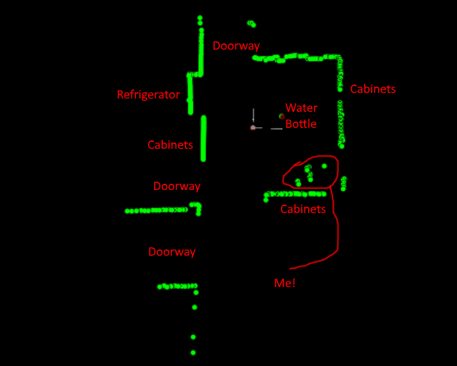
2D Lidar scan of my kitchen
As mentioned above, one option is to display lines from the lidar unit out to the point data, This is shown in the annotated scan below:
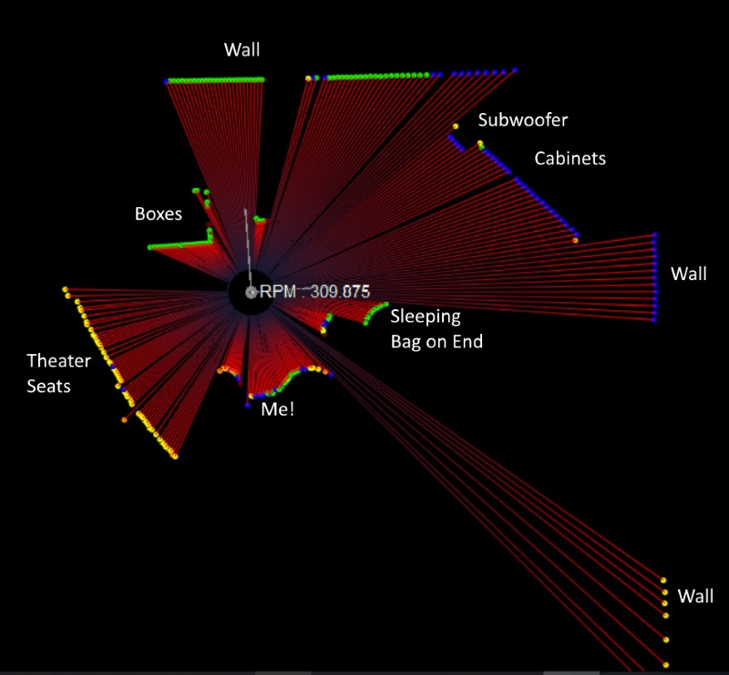
2D Scan showing lines to each data point
The display options also allow you to color code the data points based on either their intensity or their height off the ground. Examples of the same scene using these two options are shown below. In the intensity scan, you can see that nearby objects, as a general rule, show green (highest intensity), however the brown leather of my theater seats do not reflect well, and hence they appear in orange, even though they aren’t very far away from the lidar unit.
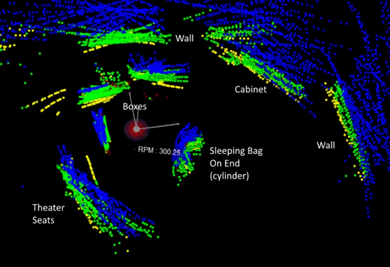
3D scan, with colors indicating height
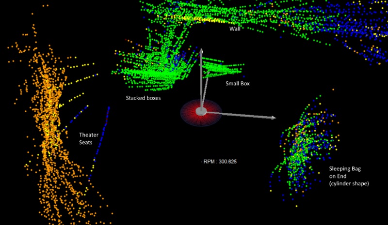
3D scan with colors depicting intensity of the return
Even after calibrating the pan and tilt angles the alignment is not perfect. This is most clearly seen by rotating the view to give a top/down view and noting that the lines for vertical surfaces do not all overlap on the display. The 3D results weren’t as good as I’d hoped, but it certainly works as a proof of concept. The 2D results are very good, given the price of the unit, and I could envision modifying the code to, for example rapidly capture snapshots and use the code to train a machine learning program.
Potential Enhancements
One clear shortcoming in the current implementation is the need to carefully calibrate the servo command values and the angles. This takes some trial and error, and is not 100% repeatable. In addition, one has to take into account the fact that as the unit tilts, the central origin point of the lidar moves, and where it moves to is also a function of the pan angle. One of the effects of this setup is that unlike an expensive multi-laser scanning unit, each 360 degree scan is an arc from low to high to low, rather than covering a fixed elevation angle from horizontal. This makes the output harder to interpret visually. The 3D scanning kit from Sweep takes a different approach, rotating the lidar unit 90 degrees, so that it scans vertically rather than horizontally, and then uses a single stepper motor to rotate the unit through 360 degrees. Both the use of a single rotation axis and the use of a stepper motor rather than a servo likely increase the precision.
With either 2D or 3D scanning, the lidar can be used indoors as a sensor for mobile robots (as that’s what it was used for originally, after all). There’s an interesting blog post about using this lidar unit for Simultaneous Location And Mapping (SLAM). I may try mounting the lidar and a Raspberry Pi on a mobile robot and give that a try.