Lidar: Coming Soon at a Price You Can Afford (part 1)

Google’s automated vehicles are instantly identifiable by the rotating lidar unit mounted on their roofs, and most other automated driving research vehicles are also using lidar, either in similar roof mounted systems (e.g., Bosch), or in multiple units, each with less than a 360 degree field of view (e.g., Carnegie Mellon). These are very powerful, 3D scanning sensors, but they don’t come cheap. According to reports, Google uses a sensor from Velodyne that costs approximately $75,000. Some of those with less than a 360 degree scan can be had at less than half that price, but you need several of them. I don’t think any hobbyists (unless they are in the 1%) are going to run out to get one to use in their robotics project. A good video showing the processed information derived from the Google car is viewable here: http://youtu.be/_EMAoiqLq9Y.

Until just a few years ago, that was about it. If you wanted to experiment with a lidar unit, you needed to shell out over $10,000. But that’s changed, and it’s starting to change even faster.

 Lidar on the Cheap

Lidar generally works by sending out a laser signal and measuring the time it takes to get a reflected signal back from an object. Like radar, you get a range and direction. this distinguishes lidar from laser rangefinders, which determine distance only (and at least one vendor,  apparently wanting to exploit the interest in lidar, advertises their rangefinder as a lidar unit). Lidars are not mass-produced, and sophisticated electronics that handle are precise at processing extremely tight time frames (the time of flight difference for a radar return from 1 meter versus 10 meters is EXTREMELY small). Very precise mechanical parts are typically required.

 The Neato XV-11

However, in 2010, Neato Robotics introduced a new robotic vacuum cleaner that got robotics hobbyists very excited. Not because they don’t like dirty floors, but because it incorporated a lidar unit as part of its navigation system. And the entire vacuum cleaner, lidar included, cost less than $400. Hobbyists got right to work hacking the lidar unit, and, while the manufacturer doesn’t sell just the lidar units, they are available on ebay and other sources for under $100 each! The interface has been reverse engineered and documented on many websites, including the XV11hacking wiki. Interface code for ROS and other platforms, e.g., arduino, have also been developed. At least one vendor, Get Surreal, sells a controller board for this unit to simplify use.

Part of the cost reduction comes from using a different approach for ranging. Rather than using time of flight for the lidar signal, the Neato unit uses  triangulation, with a laser diode emitter and an imager receiver. This eliminates the need for extremely time-precise electronics.  A technical paper on their lidar, A Low-Cost Laser Distance Sensor, is available on the web.

Obviously these units don’t compare with a $75,000 unit. Their range is on the order of 6 meters (nice for indoor or slow speed operation, but hardly something you can build an autonomous passenger vehicle around). The resolution is lower, and they produce a 2D scan, not a 3D scan. A nice, short, video demo of the type of performance you might expect is at http://youtu.be/WkW55b-WQx4. One could mount one on a tilt platform and produce a 3D point cloud from multiple scans at different angles of elevation, but it would be slower. This video shows that approach, albeit for a different lidar unit.

Neato Robotics XV-11 lidar with top removed

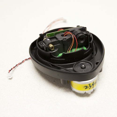
the XV-11 Unit, with the top removed. (photo source: Sparkfun)

I’ve got an XV-11 unit and controller board on order, and will report about it in part 3 of this series (which could be awhile in coming).

 RPLIDAR

The XV-11 was the first low-cost lidar unit for hobbyists, but new options at a variety of price ranges are coming available. Robopeak has introduced what appears to be a similar unit to the XV-11, the RP developed and designed for hobbyists and researchers.  Priced at $399, it includes, according to reviewers who have purchased the product, good sample drivers for several platforms, including ROS and arduinos, as well as a full SDK and good documentation (something that won’t be found when buying an XV-11 unit on ebay). For many, the greater ease of use and reduced time would be worth the price difference from an XV-11.

RPLIDAR Unit

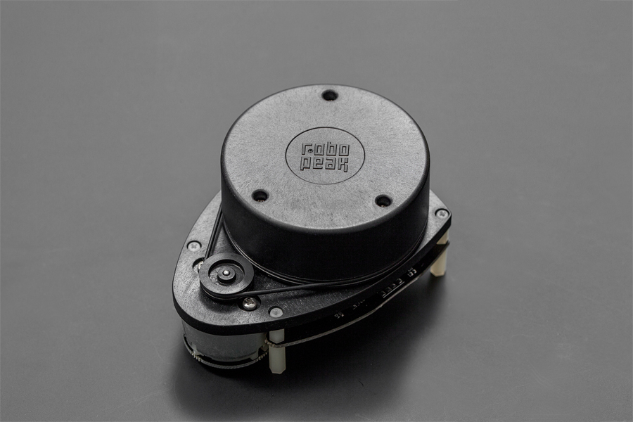
RPLIDAR Unit (photo source: DFRobot)

ADDED: LIDAR-Lite

A number of low-priced laser range-finders advertise themselves as lidars, but with this exception, I’ve looked at only systems that scan, either in 2D or 3D as lidars. While a range-finder (1D), the LIDAR-Lite has some very interesting advertised capabilities at a low price point, which might make it worth exploring putting it on a rotating platform as a lidar unit. Rather than directly measuring time of flight, as more expensive units do, or using triangulation like the NX-2, it sends out a coded waveform and, if I understand what they are saying on their website, uses signal processing to look at the shift coming back as compared with an identical reference signal.

The unit is very small (21 X 48.3 X 35.5 mm) along with a similarly sized single PCB board and costs $89. Keep in mind this is for a range-finder. You’d still have to have a precision panning platform to use it as the core of a full lidar. What makes this unit interesting is that with the $89 laser version, with optics, they claim a maximum range of 30-60 meters, and that it works outdoors in sunlight, which is, as far as I can tell, unprecedented for such a low-cost unit. 

Deeper Pockets

Part 2 of this series will discuss some of what’s available for budgets of $1,000 – $10,000, including the recently announced Velodyne Puck.

Velodyne "Puck" 3D Scanning lidar

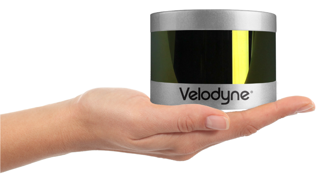
Velodyne “Puck” 3D Scanning lidar

Review and Build Report: MAKE Rovera 2WD Arduino Robot Kit, Part 2

Back to robotics! I dug out the Rovera 2WD robot that I started reviewing awhile back, added the center IR emitter/sensor and moved the left and right sensors closer to the middle, so it would be in line-following mode and loaded up the line following code. In order to have a track to follow, I printed out the pdf template patterns that Parallax has made available for their line scribbler robot and taped them down to some particle board. The first runs went quite badly, but after adjusting the damping variable in the provided code (the proportional response), and adjusting the width of the sensors and the run speed, it almost works:

As you can see, it navigates most of the course, but fails at the tricky sharp multiple curve at one corner of the track.  You can also see that it wiggles a bit going straight down the track. I need to check it out more, but it also seems to be more sensitive and react more strongly to left than to right turns.

So, while I’ve got some work to do, I’d say the Rovera 2WD robot also makes a nice robot to experiment with line following.  The provided code uses proportional control, but there’s no reason that you couldn’t add PD or full PID control logic, or drop back to bang-bang control to see how that works. The three sensors are fully adjustable in terms of lateral spacing, and you can also adjust the height if you want.

There’s also a modified version of the line-following code that transmits key variable values out while the robot is running, and a Processing program provided to graphically display the results, so that one can monitor the outputs of the sensors and the motor settings (or modify the code to track any other variable you want).  That’s part of my next step. I’ve got the Processing code up on a laptop.  I’m going to replace the complex curve with a simple one, and run the robot in some simple clockwise and counterclockwise loops to see how it behaves and see if it’s the motors or the sensors that seem to be generating the asymmetric behavior.

So, all in all, I’m quite happy with the Make Rovera 2WD kit. I’d recommend it for someone who has some experience with programming and isn’t afraid to do or learn some simple soldering. It also has a Ping ultrasonic sensor, which I’ve used on another robot, but not this one yet, so I can’t report on that aspect.

Side notes:

  1. The kit comes with an Arduino Leonardo, which many report having trouble getting uploads to work reliably on. I’m one of those. What’s working best for me is to hold down the reset key while launching the upload, then releasing the button immediately.  I think they may have been better off going with a Uno.
  2. The book doesn’t tell you to move the library functions into the libraries sub-folder in your Arduino sketchbook. I hadn’t realized that’s where they should go, so when I went from 1.0.4 that I’d been using to 1.0.5, the new version of the Arduino IDE didn’t know where to look for the robot libraries, and gave error messages.  A simple fix, but I see from various online forums that I’m not the only one who got caught by that on various projects.
  3. You can get the robot online through the Make Shed store, but also, if you have a MicroCenter near you, they’ve started to carry a lot of electronics kits, and I found mine at my local MicroCenter. Always nice to be able to give some maker business to local brick and mortar shops.

Review and Build Report: MAKE Rovera 2WD Arduino Robot Kit, Part 1

I picked up the MAKE Rovera 2WD Arduino Robot Kit the other week and have been putting it together and checking it out.  The kit comes with the book Make an Arduino-Controlled Robot that has the directions for construction and multiple projects (e.g., line following, edge detection, obstacle avoidance, etc.).  There’s also a very similar 4 wheel drive kit that uses the same book, Arduino, motor controller, etc. 

IMG_0397

There’s code you can download from the net for each project, and the author walks through and explains the code in the included book.  I like that the author talks about good practices like modular development in the book, and explains some of the nuances of using global variables with tabs when using the arduino IDE.

The kit’s primary components are the robot chassis, motors, and wheels from DF Robot, the Adafruit Motor Control Shield kit, a servo and Ping ultrasonic sensor, some IR sensors, and an Arduino Leonardo.

The kit assembles easily (but see “issues” below).  Certainly it takes less than a day, and most of that is soldering the components and connectors on the motor shield.  As someone who hasn’t done extensive soldering, I can say that soldering the parts on the motor shield kit was not difficult.

IMG_0399

The physical assembly was even easier.  I wasn’t sure of the best way to connect the sensors to the motor shield.  The kit provides ribbon cable and some connectors (and the wrong type of prototype board that doesn’t match the strip board in the instructions).  I decided the best way was to put together some 3 wire connectors using pre-crimped wires and 3×1 connector housings, as shown below:

Cables I substituted to connect the IR sensors.

Cables I substituted to connect the IR sensors.

At first I thought I’d just use some PWM cables I had lying around, but the positive and negative terminals are flipped between the IR sensors and the slots on the motor control shield, so you need to make sure to wire the connectors correctly, however you do it.

The Leonardo arduino board can be a bit ornery when first loading drivers.  I had no trouble on one of my PCs, but I had to manually load the drivers on an old laptop (even though it’s running Windows 7.  That’s not any fault of the kit, there’s a lot of discussion on line about this issue with the Leonardo board.

Once you have the robot assembled for the first time, you can run a simple test program that spins the robot.  That verifies the basic functions.  The next program in the book, the HelloRobot program, fully tests out the motor controller,

The assembled robot.  Just need to connect the IR sensors and it's ready to test.

The assembled robot. Just need to connect the IR sensors and it’s ready to test.

IR sensors, etc., so it’s a good test that you put everything together correctly.  I’m happy to report that once I fixed plugging the IR sensors into the wrong port (my bad), everything worked great.

That’s it for the initial build.  Part 2 later, when I start checking out the functionality.

Initial Bottom Line: I recommend this kit, provided you have at least a little hobby experience with electronics and arduinos — a “practiced novice.”  The troubles some have with a reliable Leonardo connection to a PC, the slight discrepancies between the kit as provided and the book, and the minor other inconsistencies in the book may, when combined, make this a frustrating experience if it’s a very first introduction to this world.

Issues:

  1. Be sure to check the on-line errata.  It’s hard, just from the description in the book, to see how to wire up the trickle charge capability for rechargeable batteries.  You can figure it out, but it’s not clear.
  2. The strip board described in the book to mount the IR sensors for line following wasn’t provided. Instead, another style of PC board was provided that doesn’t really work as intended.
  3. Read the book before building. In some sections, it begins to describe what seems like the next step, then after that step, points out it’s actually easier to do things in a different order!  That’s annoying.
  4. Not the kit maker’s fault, but it would have been great if the +, -, and signal pins on the IR sensor were in the same order as the female headers used on the Adafruit motor shield, since then you could just use a standard PWM cable to connect them.  Instead, the + and – are switched.  Instead, the kit provides ribbon cable, which, with some soldering, can be used.  I’m going to use some pre-crimped wires and crimp housings.
  5. It’s clear that the code, kit, and book went through some revisions during development, and not everything lines up. For example, one part of the HelloRobot section in the book says the robot will spin counter-clockwise when you trigger either IR sensor, while a page or two later, it says it will turn away from the triggered sensor (clockwise for left sensor, counterclockwise for right).  The latter is correct.  For software issues, when in doubt, read the actual code.
  6. If you’re looking to do navigation other than line following, you’ll need to be adding more to the robot.  There are no wheel encoders even for basic dead reckoning, so the robot has no idea where it is.  I’ve already played around with a home built robot that used a compass and wheel encoders, but no infrared sensors for edge detection or line following, so this was fine with me, but it’s something to be aware of.